

『Foxboro Magnetic Flow Meter Manual PDF: Grounding Rings and Terminal Wiring Diagrams』Related information(clamp on meter|electromagnetic meter|venturi meterrotameter|orifice meter|ultrasonic flow meter|mass flow meter|coriolis mass flow meter|coriolis flow meter|magnetic flow meter|magmeter flow meter|magflow flow meter|mag meter flow meter|electromagnetic flow meter|vortex flow meter|turbine flow meter|thermal mass flow meter|thermal flow meter|rotameter flow meter)

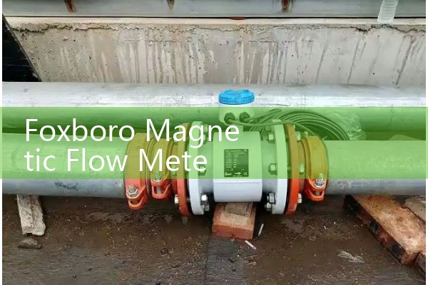
Foxboro Magnetic Flow Meter Manual PDF: Grounding Rings and Terminal Wiring Diagrams
Quick Answer: Grounding rings stop unstable readings on lined pipe, plastic pipe, and low conductivity liquids. The Foxboro magnetic flow meter manual PDF shows grounding ring placement on the upstream flange face. The terminal wiring diagram covers 4-20 mA HART, pulse output, and power isolation. Use a grounding ring when process conductivity is below 50 µS/cm or when the pipe is not electrically bonded to the liquid.
Why Grounding Rings Matter in Foxboro Magnetic Flow Meter Manuals
Foxboro magnetic flow meter manuals spend several pages on grounding ring selection. This is not an optional detail. A missing ground ring on a PTFE lined DN100 spool caused a water treatment plant in Thailand to see random 4-20 mA swings for three weeks. The signal jumped from 12.4 mA to 18.9 mA without any flow change.
A magnetic flow meter measures voltage across two electrodes. That voltage level is very small, often under 1 mV at low flow. The process liquid must provide a stable electrical reference to the transmitter ground. Metal pipe often provides that reference. Plastic pipe, concrete pipe with liner, or old rubber lined steel pipe does not. The Foxboro manual shows grounding rings installed between the flange faces for these cases.
Grounding rings also protect the electrode circuit from stray current. We have seen this on customer sites many times where a cathodic protection system on a buried pipeline caused readings to drift. A 316L stainless steel ring on each flange solved the problem. Some sites use tantalum rings for hydrochloric acid or seawater with high chloride content.
Terminal Wiring Diagrams in Foxboro Magnetic Flow Meter Manuals
The Foxboro terminal wiring diagram typically shows terminal blocks for power, signal output, pulse output, and ground. Older Foxboro 8000 series meters used 220 V AC power. Newer models accept 24 V DC. The manual separates line voltage terminals from low voltage signal terminals to prevent induced noise.
Most engineers skip this part. They land the shield wire at both ends. That creates a ground loop. The Foxboro manual usually states to connect the shield at the transmitter end only. The sensor cable shield should be terminated inside the Foxboro terminal box. The other end stays floating. We have seen a chemical plant in Malaysia run 300 meters of unshielded cable and then blame the meter for noisy readings.
For 4-20 mA HART output, the diagram shows a passive analog loop. The loop resistance must stay within the HART specification. A typical load is 250 ohms to 500 ohms. The pulse output is often open collector. A pull-up resistor of 1 k ohm to 4.7 k ohm is needed if the PLC input does not include its own pull-up.
Grounding Ring Selection for Replacement Magnetic Flow Meters
Silver Instruments supplies grounding rings that fit many Foxboro flow tube sizes from DN15 to DN600. Common materials are 316L stainless steel, Hastelloy C, and tantalum. The ring thickness matches the liner thickness. For a PTFE liner of 3 mm, we supply a 3 mm thick ring. For PFA liners, the ring is often 2 mm thick.
When a customer replaces an old Foxboro flow tube with a Silver Instruments electromagnetic flow meter, we ask for the original manual or nameplate photo. The Foxboro manual PDF gives the flow tube length, flange standard, and grounding ring style. We copy the wafer thickness and bolt pattern. This avoids new pipe spool work. A distributor in Chile recently ordered six
For aggressive media, do not guess the electrode material. Send us your process fluid, chloride concentration, operating temperature in degrees Celsius, and pressure in bar. Silver Automation Instruments can select the right liner and electrode combination. We supply remote or compact versions. Both support 4-20 mA HART, RS485 Modbus, and pulse output.
Common Wiring and Grounding Errors We Find on Site
One common error is painting over the grounding ring contact surface. The ring is metal but the pipe painter covers everything. The electrical contact then fails. Another error is using a grounding electrode instead of a grounding ring on a lined pipe. A grounding electrode helps, but a full ring gives a more stable reference for low conductivity liquids like pure water or condensate.
Some technicians connect the signal cable shield to the same terminal as the power ground. That couples 50 Hz noise into the electrode signal. The Foxboro terminal wiring diagram keeps power ground and signal ground separate. The manual often labels them PE and SE. PE is protective earth. SE is signal earth. Do not short those two terminals in the field.
In practice, you can check the installation with an ohmmeter. The resistance between the grounding ring and the transmitter ground lug should be under 10 ohms. If the value is higher, clean the flange face and re-tighten the bolts. This simple check prevents hours of troubleshooting.
Five Questions Engineers Ask Us About Foxboro Grounding Rings and Wiring
Do I need grounding rings if the pipe is metal?
No. A clean metal pipe with a conductive process liquid usually provides a sufficient electrical reference. Add grounding rings if the metal pipe is painted, lined, or isolated by gaskets.
Can I reuse the existing Foxboro terminal box when installing a Silver Instruments meter?
The terminal layout may differ. We can provide a wiring cross reference from the Foxboro manual to Silver Instruments terminals. Send us a photo of the old terminal block and the Foxboro model code.
What conductivity is too low for a magnetic flow meter?
Most magnetic flow meters need a process liquid conductivity above 5 µS/cm. Some high performance models work down to 1 µS/cm. For demineralized water below that level, an ultrasonic or Coriolis meter may be a better fit.
Does a grounding ring change the flow profile or cause pressure drop?
A wafer style grounding ring adds a small flow restriction. The inside diameter matches the pipe bore, so pressure drop is minimal. For slurry service, order rings with the same hardness as the liner material to avoid premature wear.
How do I get a price for replacement grounding rings or a new magnetic flow meter?
Send us your pressure (bar), temperature (°C), pipe size (DN), and flow range. We reply with a quotation and lead time. Our direct line is +86-25-68650347. WhatsApp is +86-25-52155837. WeChat is +86 15365082610.
Silver Automation Instruments supports Foxboro magnetic flow meter replacement projects in Southeast Asia, Oceania, Latin America, Africa, and the Middle East. We keep stock of common grounding ring sizes DN50, DN80, DN100, DN150, and DN200. For special sizes, production time is usually 7 to 10 days. A clear photo of the Foxboro manual terminal wiring diagram helps us confirm the correct signal and power connections before shipment.
 Hot Blog
 Related AD