

 Current position > Product detail
『DN10 Flow Meter Piping Requirements for Stable Readings』Related information(clamp on meter|electromagnetic meter|venturi meterrotameter|orifice meter|ultrasonic flow meter|mass flow meter|coriolis mass flow meter|coriolis flow meter|magnetic flow meter|magmeter flow meter|magflow flow meter|mag meter flow meter|electromagnetic flow meter|vortex flow meter|turbine flow meter|thermal mass flow meter|thermal flow meter|rotameter flow meter)
 ```html
DN10 Flow Meter Piping Requirements for Stable Readings
Quick Answer: For a DN10 flow meter to deliver stable, repeatable readings you must follow strict piping rules. In most cases you need 10 pipe diameters of straight run upstream and 5 downstream, full pipe condition at all times, zero mechanical stress on the meter body, and rigid supports to isolate vibration. If your pipe is smaller than DN10, use a concentric reducer carefully machined to avoid flow profile distortion at the sensor inlet.
Many engineers first assume a DN10 meter is plug and play. In practice, small line sizes punish poor piping far more than DN50 or DN80 installations. A slight misalignment, a bubble trapped in a horizontal run, or a pump pulsation 300 mm away can make the reading jump by 5 percent or more. We have seen this on customer sites many times, especially in chemical dosing skids and pilot plants across Southeast Asia.
Silver Automation Instruments supplies Coriolis, magnetic, vortex, and oval gear flow meters in DN10 size. Each technology has its own piping sensitivity, but all of them share one demand: the pipe must deliver a clean, fully developed, single phase flow to the measuring element. Get that right and a DN10 meter will give you 0.1 percent repeatability for years.
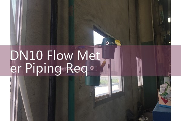
For a Coriolis meter DN10, the most critical rule is mechanical decoupling. The meter must not act as a pipe support. Use pipe clamps on both sides of the meter, placed as close to the process connections as the manufacturer allows, usually 50 to 100 mm away. Never let the meter hang on the tubing. We recommend rigid brackets bolted to a concrete wall or a heavy steel frame. A customer in Thailand who runs a silicone oil blending process forgot this step, the meter vibrated with a nearby gear pump, and the mass flow reading drifted by 2.3 kg/h on every stroke. Adding two strut clamps and a short flexible hose section before the meter solved it within an hour.
With a magnetic flow meter DN10, the pipe must remain completely full at all times. Even a small air pocket, maybe 3 mm across, can break the electrode circuit. For horizontal installation, place the meter in a low point of the pipe run. For vertical installation, flow must go upward, so the liquid keeps the electrodes wetted. Grounding is non negotiable. Use grounding rings or a built in reference electrode if the pipe is lined or non conductive. In a wastewater reuse plant in the Philippines we specified a DN10 magmeter with Hastelloy electrodes and PTFE liner, and the installers ran a short section of PVC pipe without grounding rings. The empty pipe detection tripped every morning. Adding stainless steel grounding rings on both flanges fixed the noise instantly.
When you install a vortex flow meter DN10, straight run requirements increase dramatically because of the small bluff body. We advise 20 diameters upstream and 10 downstream if possible. More if the upstream disturbance is a control valve. Use schedule 80 pipe or better to match the internal diameter and avoid any step change at the gasket. If you must reduce from DN15 to DN10, use a 15 degree included angle concentric reducer, not a sudden step.
For oval gear flow meters DN10, the main enemy is particulate contamination, but piping matters too. Mount the meter so the gears sit horizontally. If the meter is installed in a vertical line, ensure flow goes downwards, never upwards, to prevent air locking. Strainer mesh of 100 microns or finer should be installed no more than 300 mm upstream. A paint manufacturer in Indonesia ran a solvent based ink through a DN10 oval gear meter and saw 8 percent low readings after three days. The cause was a partially clogged strainer that created a pressure drop and induced cavitation. A simple strainer clean brought the reading back to spec.
Thermal mass flow meters in DN10 also need special attention. The sensor probe must be centered in the pipe. Any eccentricity changes the heat transfe
Across all technologies, the connection style matters. DN10 often uses compression fittings, NPT threads, or sanitary tri clamp connections. Avoid excessive PTFE tape on NPT threads because a shred of tape can break loose and stall an oval gear meter or disturb a vortex shedding frequency. Use a suitable thread sealant rated for your process fluid and apply it only on the male threads, first two threads left clean.
Vibration isolation is not optional. In a DN10 line, even a small pump at 50 Hz can resonate the meter mounting bracket. We have measured a 6 Hz vibration amplitude of 0.15 mm on a poorly supported Coriolis meter and the mass flow uncertainty went from 0.1 percent to 0.9 percent. Bolt the bracket to a mass of at least 10 kg. If you cannot avoid pump pulsation, install a pulsation dampener. For gas flow on DN10, a dampener is almost mandatory.
Temperature effects in small meters can surprise you. A DN10 meter body heats up quickly if you flush it with 120 °C CIP fluid. If the meter is rigidly connected to a cold frame, the thermal expansion creates stress and zero shift. Always allow for pipe expansion loops or flexible connectors when the process temperature varies more than 40 °C from the ambient during cleaning cycles.
Testing the installation before full startup is a step most engineers skip. Simply fill the pipe with water at a known stable flow rate, record the meter output for 2 minutes, then switch to a different flow rate and repeat. Compare the standard deviation. If it exceeds 0.2 percent of rate on a Coriolis or 0.5 percent on a magnetic, you have a piping induced error. Find it before you rely on the meter for batching or dosing.
If you are specifying a new DN10 meter for a skid, send us your flow range (kg/h, L/min or Nm³/h), fluid type, temperature (°C), inlet pressure (bar), and pipe connection type. We will recommend a meter model and piping layout that meets the 10 diameter straight run rule from day one. Many of our customers in Latin America and the Middle East get a GA drawing from us with the meter and piping dimensions before they even cut pipe. This avoids rework on site.
FAQ
What is the minimum straight run for a DN10 Coriolis flow meter? Most DN10 Coriolis meters do not require straight runs by design, but we still recommend 5D upstream and 3D downstream to isolate mechanical stress and reduce external vibration coupling.
Can I install a DN10 magnetic flow meter between two elbows? Not without precautions. You need at least 5 diameters of straight pipe upstream of the electrode plane. If you cannot achieve that, use a flow conditioner or contact us for a meter with a shaped liner that reduces sensitivity to velocity profile distortion.
Why does my DN10 oval gear meter read zero even though liquid is flowing? Nine times out of ten it is an air lock. Bleed the high point vent thoroughly. If the pipe slopes upward, air gets trapped above the meter gears. Re pipe so the meter sits at the lowest point or add an air release valve immediately upstream.
Do I need grounding rings on a small plastic pipe magmeter? Yes. Without grounding rings or a grounding electrode, the signal will be noisy and the meter may show empty pipe or erratic flow. Always install stainless steel or Hastelloy grounding rings on both sides of a non conductive pipe.
Can Silver Instruments provide a turnkey DN10 flow meter with piping spool? We offer pre assembled meter spools with correct pipe sections, reducers, and supports for DN10 in Coriolis and oval gear types. Tell us your pipe schedule and flange rating, and we ship a calibrated assembly ready to weld or screw into place.
```